Selection of the power supply
The power supply within a motor control system is often underestimated although it is the initial link of the power chain which has to provide and buffer energy for high dynamic motor motion.
Power supplies in use for notebooks seem to be an attractive choice concerning size and price but actually these kind of power supplies can be the root cause of “Overvoltage” or “Undervoltage” errors or “strange” motor control behaviour. Such compact-sized power supplies are not designed for motor control applications and have less internal capacitance for providing and buffering energy in case of dynamic motor control demands. This can result in short-time voltage breaks triggering different motor controller error states then.
The use of power supplies designed for industrial applications is generally recommended. Some of these are even optimized for motor applications. These power supplies have big internal capacitors to provide additional energy during acceleration and to buffer reversed energy during deceleration phase.
Conclusion:
A proper choice of an industrial power supply can already solve problems and error messages caused by reversed energy.
Additional capacitors
An external capacitor close to the controller can help to buffer the reversed energy and prevent a fast voltage increase. Typically there are capacitors of 47'000 uF in use for that. It is important that the capacitor’s voltage rating can cope with the maximum supply voltage level plus some reserve (of at least 20-50%) too.
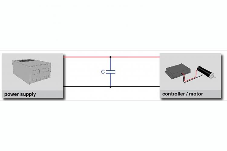
Mixing power consumers and "generators
If there are motors and other power consumers present within a system, try to group these loads in a way so that the same power supply is in use for a motor which is reversing energy and other loads or motors which are consuming energy at the same time. Worst case is always if there is one or more motors connected to one power supply and all of these motors are operated in the deceleration phase at the same time. Some consuming loads will be appreciated counterparts of motors generating energy.
Configuration of deceleration profiles
a) Deceleration ramp
If you are open to reduce the steepness of deceleration ramps without any drawback concerning your application’s requirements, this can solve “Overvoltage” problems without any additional measures.
b) Multiple decelerating drives
If there are multiple drives in use within a system and all of these are starting deceleration at the same time, this results in a high initial peak of returned energy. If it is possible to start the deceleration phase of each motor just a little bit time-shifted, this can improve the situation. The biggest amount of energy is always returned at start of deceleration because it is still the state of full speed then (-> Energy is proportional to inertia or mass and speed^2). This means that starting deceleration phase of different motors stepwise results in splitting up the total amount of reversed energy over a longer period of time and getting rid of an extreme high peak in the beginning.
Supply voltage
The supply voltage defines the margin before “Overvoltage limit” of the controller is reached. Let us assume that there is a supply voltage of 48V in use. If this supply voltage is not necessary to reach the maximum motor speed required by an application, reducing the supply voltage (based on motor speed requirements) results in a broader margin before the “Overvoltage limit” error state of the controller (e.g. capable of up to 50V DC) is hit.
Shunt regulator
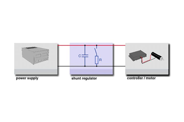
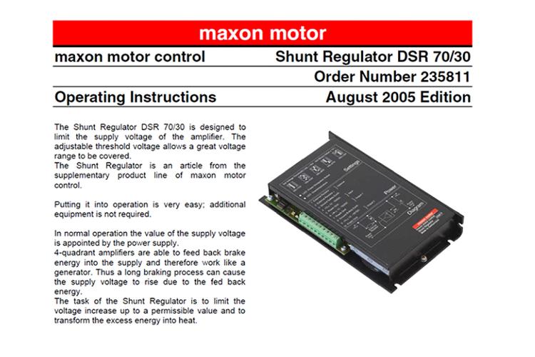
If some or even all of the mentioned measures still cannot fully solve the problem due to the amount of reversed energy, one or more shunt regulators (or so-called brake choppers) have to be installed to consume the reversed energy, e.g. "maxon DSR 50/5" or "maxon DSR 70/30".
Image below: There can be one shunt regulator in use for multiple drives. The shunt regulator has to be placed in the supply voltage line in between the power supply and the controller.
