Moving loads with an electrical drive is usually done with a system that uses an encoder on the motor shaft to provide the position and velocity information for control. High encoder resolution and precise detection of the motor shaft reaction are essential for dynamic position control. From the point of view of the application, however, it is ultimately the precision of the output-side load movement that is critical for the quality and dimensional accuracy of the goods produced. Gearheads, spindles, and drive belts can have a negative effect on this. Depending on the direction of movement, the gear backlash may result in a different load position on the output side. Elasticity may cause delays and oscillations at the start or stop of the movement. The first solution that comes to mind is to mount the encoder on the output shaft, instead of the motor shaft. However, rather than success, this results in even worse system performance.
In the case of a mechanism with backlash or elasticity, dynamic and precise load positioning requires the use of a system in which control is based on two encoder systems:
• One rotary encoder, the auxiliary encoder, is rigidly connected to the motor shaft. It should already be part of the motor combination.
• Another encoder, the main encoder, is connected to the moved load on the output side.
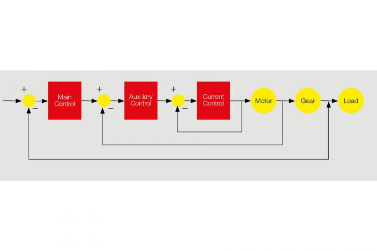
Figure 1 Dual loop architecture consists of three integrated feedback loops.
To process the signals from these two encoder systems, dual loop control is required. maxon’s EPOS4 positioning controllers augment this dual loop control with a second-order filter and a gain scheduler to counteract mechanical resonance and gear backlash. The EPOS Studio commissioning software provides a Regulation Tuning tool which automatically determines parameters for the complex controller structure. It also plots the transfer function of the drive.
Control architecture
EPOS4 uses a cascade control structure for the dual loop control (see Figure 1):
• The innermost control loop provides field-oriented control (= FOC) of motor current based on the motor current measurement as a feedback signal.
• The middle control loop (auxiliary control) controls the motor speed based on the encoder on the motor shaft.
• The outermost control loop (main control) controls the position of the load based on the encoder system on the load.
A detailed view of the EPOS4 dual loop control structure is shown in Figure 2.
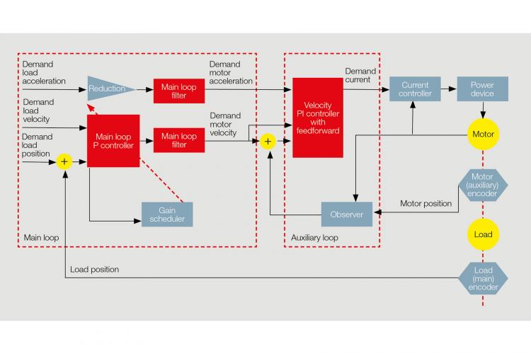
Main control loop
The main control loop is made up of a proportional (P) controller, a gain scheduler, and a second-order filter (the main loop filter). A path planner supplies the desired position of the load and its desired velocity and acceleration as input variables for the main control loop. Another input variable is the current position of the load, as measured by the encoder on it.
• Gain scheduler
The EPOS4 dual loop control uses the gain scheduler to eliminate negative effects from gear backlash. The gain scheduler does this by automatically adjusting the P gain of the main control loop. If the tracking error—the deviation of the actual load position from the desired position—is too large, a high P gain will be applied, resulting in rapid reduction of the error. As the tracking error becomes smaller, the P gain is reduced as well, so that oscillation does not occur in the drive, despite gear backlash.
• Main loop filter
If there is a certain amount of elasticity between the motor and the load due to couplings, belts, or long spindles, resonant frequencies could cause amplifying oscillations. These could increase to the point where control becomes unstable. In order to prevent this, the EPOS4 dual loop controller uses a second-order filter, of the notch filter type. This filter suppresses the resonant frequency range in the output signal from the main control loop, thereby preventing harmonic oscillations in the drive train.
Auxiliary control loop
The auxiliary control loop consists of a proportional-integral (PI) controller with feed forward (FF), and an observer that estimates the motor speed from the position data of the motor encoder and the motor current measurements.
Auto-tuning procedure
To simplify commissioning, maxon’s EPOS Studio software features an integrated auto-tuning wizard to determine and validate the parameters of the dual loop controller. The auto-tuning procedure consists of two experiments that are carried out automatically.
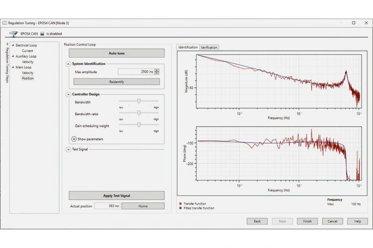
Figure 3 Example of a transfer function identified using EPOS4, with resonance.
• Experiment 1 triggers oscillations of the motor shaft. These oscillations are used to determine the mass inertia, the torque constant, and the friction in the motor. The parameters for the auxiliary loop controller and observer are then calculated on the basis of the data identified.
• Experiment 2 is used to calculate the parameters for the main control loop and the notch filter. A PRBS signal (= Pseudo-Random Binary Sequence) is used to excite the plant. Based on the resulting input-output data, the transfer function is identified and presented as a Bode plot (see Figure 3).
The Bode plot can be exported. It assists control technicians in system analysis in optimizing the mechanical design, and in manual adaptation of the control for specific applications.
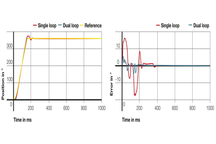
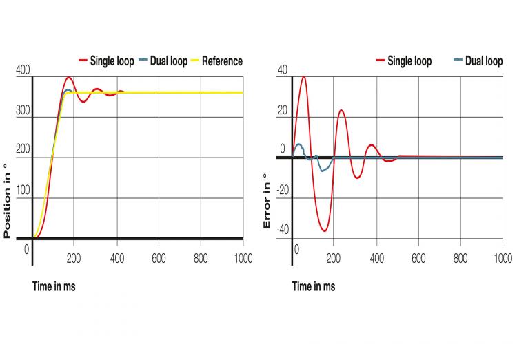
Comparison of single loop control and dual loop control
The following graphs show the differences in reference response and tracking error for a system with gear backlash (Figure 4) and a system with an elastic coupling (Figure 5). The graphs compare single loop control with an encoder on the load, and automatically tuned dual loop control with an encoder on both the motor shaft and the load.
Dual loop control is a way of making drive systems more precise and more efficient. maxon offers not only all the components required, but also a great deal of experience in consultation—from the initial idea and the system design through to full-scale commercial production.