The feedback sensor of choice for many application with small motors is the digital incremental encoder. This blog series starts with a reconsideration the most important encoder properties before looking at the selection for position and speed control applications in more detail.
What are the typical requirements?
Each application is different. The main task may be position control or speed control. The level of accuracy in speed or position control can be very different and should be defined before encoder selection. Speed control at low speed (below 100 rpm) needs a better feedback than speed control at high speed (1000 rpm and above).
The load may be coupled directly onto the motor or there is a mechanical transformation system such as a gearhead, a screws or other. Encoders are typically mounted on the motor shaft, but can also be on the load itself. The mechanical properties of the transformation mechanism influence encoder selection: gear reduction and mechanical play have to be taken into account.
Environmental conditions such as temperature, vibration, electromagnetic interference may also have an influence on encoder selection. Optical encoders, for example, should be protected against dust. Magnetic encoders may be sensitive to external magnetic fields – including those of the motor – and may require shielding.
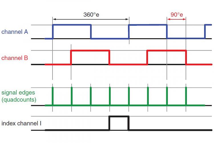
The signals of a digital incremental encoder. Counting the state changes (the signal edges of channels A and B) results in a 4-times higher resolution than the number of counts per turn on one encoder channel.
What are the key properties of incremental encoders?
The characteristic parameter of an incremental encoder is the number of rectangular pulses per motor revolution. Typically, there are two channels delivering the same pulse number. The two signals have a relative phase shift of one quarter of a pulse length. This arrangement allows the detection of the direction of motor rotation and gives 4 distinctive states per pulse. Sometimes, these states are called quadcounts. They represent the real resolution which is 4 times higher than the number of pulses on one channel. An encoder with 1000 cpt (counts or pulses per turn) gives 4000 states per turn or a nominal resolution of 360°/4000 = 0.09°.
Observe: When discussing the resolution of an encoder, make sure that everyone talks about the same: the number of pulses per channel (cpt) or the number of states (the quadcounts).
The encoder resolution can vary in wide range. From a very simple 1 cpt (or 4 states) encoder that can be used merely to detect motion, up to several 10’000 cpt for highly accurate position or speed feedback. There are many factors that influence the achievable encoder resolution: the underlying physical principle (optical, magnetic, inductive …), the primary signal type (analog or digital), the signal treatment (e.g. interpolation), and the mechanical layout to name a few. This blog, however, is not about encoder design, but about how particular application control requirements can be matched by suitable encoders.
How accurate are encoders?
Resolution – the number of states – gives the nominal accuracy, the position is known within an error of 1 state. However, encoder pulse lengths may vary due to mechanical tolerances (e.g. shaft runout, length of magnetic poles and others). The pulses in one range of motor rotation may be shorter than the pulses of other ranges. As a result the measured position deviates from the real position in a periodic way over one motor revolution.
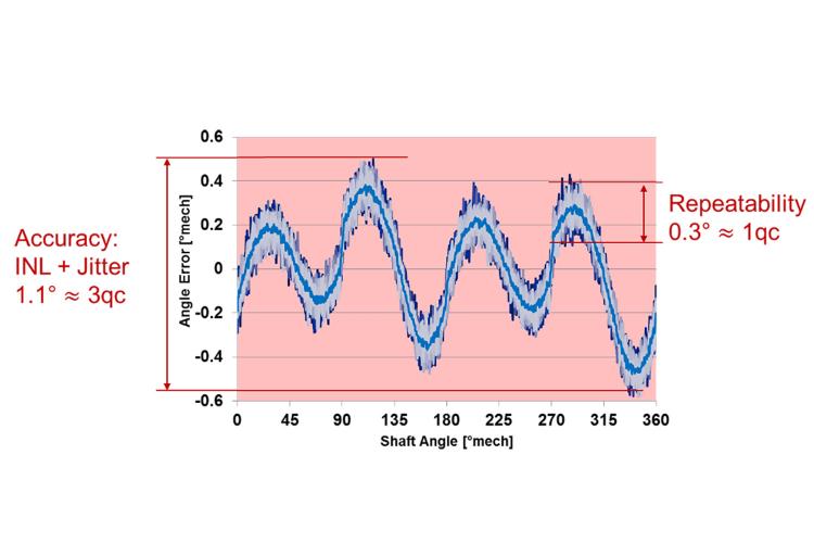
The maximum deviation (peak to peak) is called Integrated Non-Linearity (INL). INL is important in applications that require absolute position accuracy. Repeatability – i.e. always reaching the same position for a given set value - is not affected by INL. Repeatability is rather a question of signal jitter that typically amounts to less than 1 state.
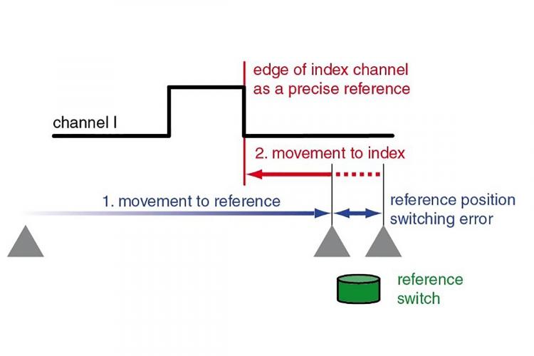
Improving the accuracy of the reference position by an additional move to the edge of the index channel signal.
Incremental encoders and absolute positions?
Incremental encoders just give position changes. For absolute positioning, a reference or home position must first be established. This is achieved by moving the mechanism to an external reference; this could be a mechanical end stop or a limit switch.
Some encoder feature a third channel with one pulse per turn. The edges of this Index channel give absolute position references within one turn. The limited accuracy of external references can be improved by an additional move to one of the Index channel edges. However, observe that the Index channel is not a prerequisite for positioning. In fact, machine builder try to avoid using the Index for referencing because it requires new calibration if a motor-encoder unit has to be replaced. Furthermore, some controllers use the index channel to crosscheck the encoder signal and supervise the encoder counts per turn.
What to observe when transmitting the signal?
Line Drivers are recommended for transmission over long lines and for a better signal quality. For positioning, a line driver is almost a must in order to avoid to miss encoder pulses.
Line Drivers generate inverted signals (Ā, B̄, Ī) for each channel (A, B, I). Each signal pair is transmitted together and the difference is evaluated, thus filtering out any electromagnetic interference during signal transmission. As a beneficial side effect, the signal quality is improved, the signal edges are more clearly defined and the driver function enables the transmission of the signal over longer distances (up to about 30 m).
Encoders need a minimum supply voltage. On long encoder lines, the line resistance and the corresponding voltage drop can be an issue. Check the cable cross section and the supply voltage.
Environmental conditions, robustness
The standard operating temperature range of encoders is in the range of -30°C to +100°C. This covers most of the applications and the heat produced by the motor.
In strongly vibrating applications and with mechanical shocks, a robust mechanical housing and a good strain relief of the cables are important.
While optical encoders are less sensitive against electromagnetic interference magnetic encoders need a good shielding against magnetic stray fields. If the housing is not well closed and tight, optical encoders are sensitive against dust.
In next blogs I would like to look more precisely at encoder selection for positioning and for speed control.