Standard cables in use by motors and sensors might just have a length of 30 cm up to 3 m. Sometimes this is not long enough especially if controllers are installed in a cabinet of a machine which might be placed some meters away or even in another room.
There is no general answer concerning the maximum cable length. A cable length of up to 10 m can be handled without any problems if some special measures are taken into account. Even cable lengths up to 50 or 100 m have been successfully in use if anything is installed in a perfect way and the signal quality is checked and confirmed during initial commissioning.
Special measures to think about in case of long cable lengths
Quite often the first spontaneous thought might be that the signal’s voltage drop on long wires might be the critical point. In fact this is not the truth because sensor signals often just have to fulfill the TTL specification which accepts a “High” signal already at a voltage level above 2.1V. The required signal level is specified in the “Hardware Reference” of the maxon controllers in the chapters about the encoder and hall sensor inputs.
1) Sensor’s supply voltage
Encoders typically have a tight tolerance concerning the supply voltage. In case of a 5V +/-5% specification this means that at least 4.75V has to be present at the encoder’s supply voltage input to ensure its operation. The voltage drop of long cables can get critical from the supply voltage’s point of view. If the supply voltage is not sufficient, the sensor signals will not be present, wrong, or sometimes missing. The root cause of missing pulses is often the supply voltage and not the signal level like expected. Therefore it is important to ensure that the specified supply voltage is present at the encoder’s connector. This can be improved by using thicker wire gauges inside the cable. Actually such thicker wires are just required for the supply voltage and GND wire. The voltage drop of the sensor wires is not so critical like mentioned above.
The drawback of generally thicker wires is that these make cables less flexible, heavier, and more expensive. Cables with mixed wire gauges are very special designs and even more expensive. There is a simple solution to overcome these drawbacks:
Use more than one wire for the supply and GND
Buy a cable with more wires than actually required, e.g. a cable with 10 or 12 wires instead of just 8 wires typically required by an encoder. Use 2 – 3 wires for the supply and GND. Such cables are standard, most cost-efficient, and still are more flexible than a cable with thicker wire gauges
2) Sensor’s signal type
There is the general recommendation to use encoders with differential signal lines to improve noise immunity and reduce the risk of wrong pulse detection especially in case of position control. This general requirement gets even more important in case of long cables:
Use only encoders with differential signal lines!
Hall sensors quite often do not offer differential signal lines but are not so critical concerning single wrong pulses. Anyway the risk for signal noise and negative effects in case of hall sensors also have to be judged and depend on other mentioned measures too. If this risk or error states by the controller concerning the hall sensor signals are present, think about installing a line driver close to the motor and a line receiver close to the controller for the hall sensor signal lines.
3) Reduce EMI influence
The risk of an EMI disturbance is strongly increased in case of long signal lines, e.g. it is often not fully clear what other cables might be close to signal cables inside a machine. It gets even more important then to use shielded cables for all power lines of inductive loads like motors, relays, main contactors, pumps, fans, but also starters of neon tubes just to mention some.
- Do not mix signal and motor power lines inside one cable!
- Do not use flat cables! These cable types are more critical concerning EMI and offer less chance for any shielding.
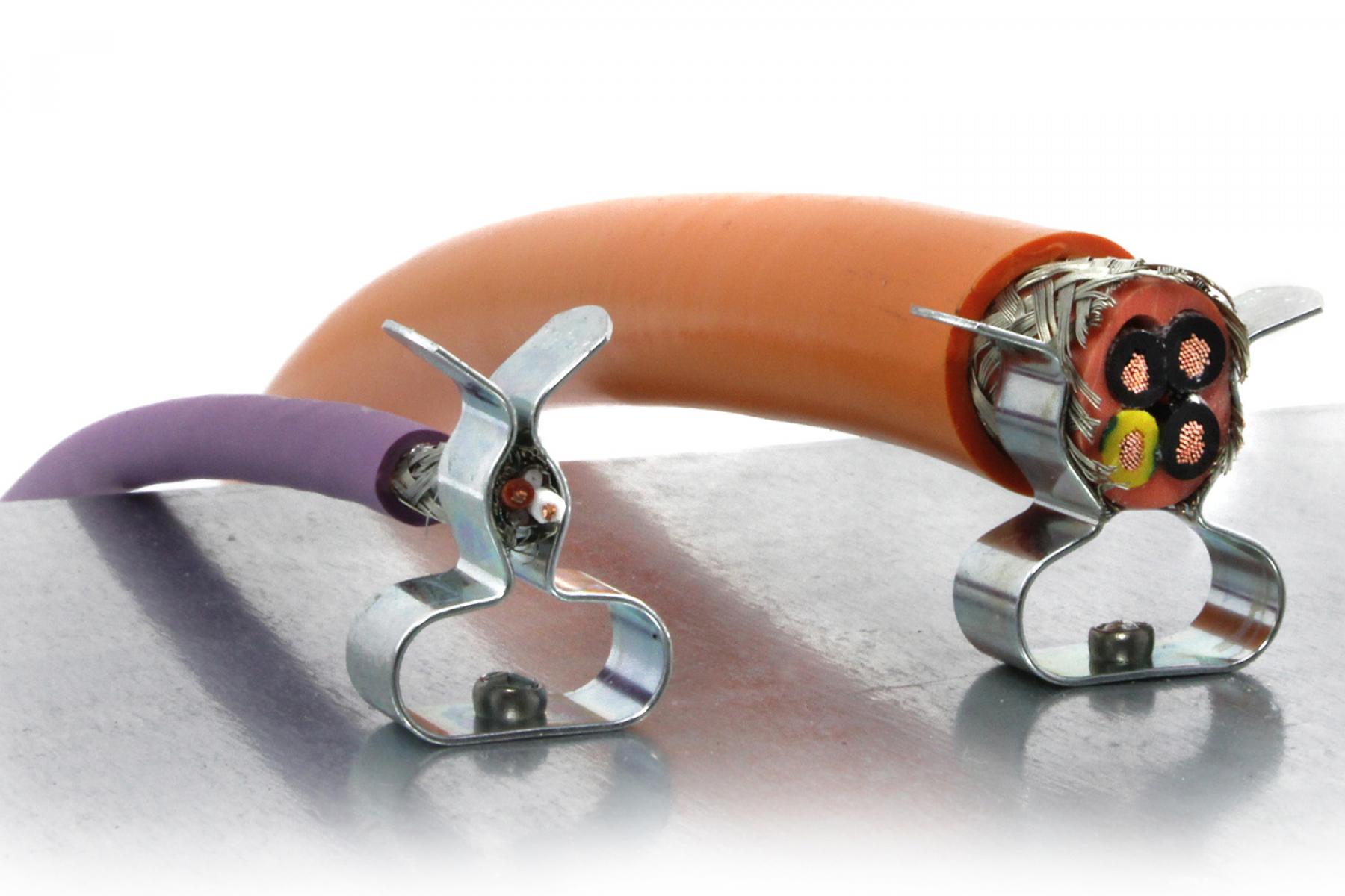
- Use shielded cables for power and motor lines!
- Attach the shielding to Earth using earth clamps at both ends of the long cable!
- Try to separate motor cables and signal or sensor cables and do not put them on top of each other (if possible).
Taking care of all these measures and finally checking signal quality during initial commissioning will help to reduce the drawbacks and risks of long cables during operation.